Privacy statement: Your privacy is very important to Us. Our company promises not to disclose your personal information to any external company with out your explicit permission.
The use of five-axis machining offers many benefits in several ways. By analyzing equipment, processes and clamping, especially cutting tools and cutting, you can benefit from it.
In addition to the ability to perform certain features through full five-axis machining, the five-axis machining process can also be selectively simplified. This includes the use of three plus two axes, or sometimes only three axes, especially for various roughing, semi-finishing and milling operations.
Although some part features have a hyperbolic profile and move along five axes at the same time, using the right tool and maintaining the proper constant amount of tooling, you can efficiently machine almost any curvature.
The main benefits of using 5-axis machining
Obviously, it is possible to efficiently obtain complex three-dimensional (double-sided) part features, which are not only highly accurate, but also have excellent surface quality. Generally, only one clamping and a minimum of cutting operations are required, the cutting time is greatly shortened, and the tool overhang is always kept as short as possible. In addition, the metal removal rate is often increased and the risk of tool collision is controllable. For five-axis machining, simultaneous machining, and three- and two-axis machining, cutting tools and process selection are key factors in achieving successful results. Compared with the three-plus-two-axis machining, the process selection during linkage machining is more important because the former is less challenging and can be treated as a three-axis process.

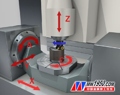
Figure 1 (Picture No. 101108)
Five-axis CNC machining is based on the ability of the machine to move on five axes to create 3D part shapes. Moreover, true five-axis simultaneous machining means that in addition to being able to position the tool along the axis of rotation, the tool can be fed along these axes during cutting. The inevitable result is that the machine tool can form complex part shapes in one setup. In addition to the three basic axes (x, y and z), there are two additional axes (b and c, or sometimes a and c, depending on the machine configuration), around the z-axis and around y during cutting The axis (or x and y) rotates. When the machine spindle or table is fixed at an angle and is machined in three-axis mode, it is three-plus-two-axis machining. From a machine tool point of view, there are several ways to achieve five-axis machining: a five-axis machining center, a tilting table arrangement, or a spindle head attachment.

Figure 2 (Picture No. 081744)
Five-axis linkage machining of the impeller with CoroMill Plura solid carbide end mill
The texture created by the rotating tool on the surface of the part is a major consideration. For this purpose, the plunging angle and the tool tilt angle are achieved by the CAD-CAM program and should be considered when designing the clamping method. Not only the main declination of the cutting edge, but also the amount of tool knives and the size of the back angle will have an effect, so as to avoid back-cutting.
The plunging angle can be measured from the angle between the tool center line and the perpendicular of the tool contact point perpendicular to the workpiece surface at the feed direction. In many cases, this value will remain constant and match the recommended value of the tool used, but can be changed programmatically if allowed by the CAM. With a fixed plunging angle, the tool can be tilted at a predetermined angle relative to the surface of the part throughout the feed direction. The plunging angle is based on the smallest inner radius on the surface and the effective diameter of the tool.
The inclination of the tool is based on a plane perpendicular to the feed direction, so the plunging angle can be measured from the centerline of the tool and the perpendicular perpendicular to the surface at the cut. Constant plunging angles at each point are critical to creating curved surfaces and concave part surfaces. Although point milling consumes more cutting time and may shorten tool life, it is safe for concave surfaces and hyperboloids. the way. The tool is always in contact with the workpiece at its fillet radius (the position of the contact point varies according to the radius of the tool along the radius of the tool), and a three-dimensional surface can be created by continuous machining. Point milling with end mills is suitable for roughing, semi-finishing and finishing operations.
November 18, 2024
November 11, 2024
E-posta denna leverantör
November 18, 2024
November 11, 2024

Privacy statement: Your privacy is very important to Us. Our company promises not to disclose your personal information to any external company with out your explicit permission.

Fill in more information so that we can get in touch with you faster
Privacy statement: Your privacy is very important to Us. Our company promises not to disclose your personal information to any external company with out your explicit permission.